Sunday, December 21, 2008
Description of CRRCSIM
A Guided Tour of CRRCsim by Mark Drela 5 Dec 00
------------------------
The CRRCsim Project was kicked off when Jan Kansky announced
on the CRRC Email List that he was working on porting a freeware
flight simulator out of NASA Langley to run on his home computer.
He was looking for a means to generate the aero data for
any arbitrary airplane to plug into the simulator.
Cooincidentally, I had the means to generate such aero data
and was looking for a simulator to plug it into... A flurry
of email code exchanges between me and Jan followed.
The initial CRRCsim version was announced by Jan shortly thereafter.
During the quick development, I discovered that
the "guts" of the Langley simulator code which
computed the aerodynamic forces had serious limitations.
It assumed that the aircraft didn't deviate
very much from a single cruise speed, and performed only
benign maneuvers. If these restrictions were violated,
the computed forces would be seriously in error,
and unrealistic flight behavior might result.
I completely replaced the Langley code with new code
which does not have such restrictions. Even relatively
violent maneuvers can now be simulated with reasonable
accuracy.
The writeup below gives a brief overview of flight simulator
basics. The features specific to CRRCsim are
then described at the end.
Simulators 101
--------------
All flight simulators use the same basic approach
to keep track of the aircraft. At any instant
in time, the simulated aircraft has some location
and some orientation. These are defined by six
numbers: the aircraft's x,y,z coordinates (3 numbers),
and by its heading, elevation, and roll angles (3 more numbers).
These six quantities are used by the graphics routines
of the simulator to display the aircraft at that instant.
As the quantities change in time at some fast rate,
the airplane's position and orientation changes,
so that it appears to fly -- just like in a movie.
The main problem for the simulator program is to rapidly
calculate the correct sequence of the six quantities,
according to the airplane's properties and the pilot's
control inputs. The more accurate this calculation is,
the more realistic the plane's flight behavior appears.
Updating all six quantities requires calculation of the forces
and moments (torques) on the aircraft. Some, like gravity forces
or gyroscopic moments, are easy to compute. They only require
knowledge of the mass and inertias of the aircraft, which are
specified by the user. Other forces, like thrust, are set
directly by the pilot himself. The remaining forces and moments
are aerodynamic in origin, and are the most difficult to compute.
CRRCsim simulator
-----------------
CRRCsim computes aerodynamic forces and moments from data
generated by a "Vortex Lattice" program AVL, which in turn
takes its input from a geometric definition of the aircraft.
The geometric definition consists of chords, dihedral, twists,
airfoils, control surfaces, etc. which are specified by the user.
AVL is in effect a numerical wind tunnel which simulates
the airflow over the specified configuration and computes
the force and moment data. For example, it computes the
CL versus angle-of-attack curve which might otherwise be
measured in a wind tunnel. AVL actually computes about
20 such curves --- 3 forces and 3 moments, versus 2 flow angles
(angle-of-attack and sideslip angle), and 3 rotation rates
(roll, pitch, yaw rates), in appropriate combinations.
The AVL simulation accounts for most of the important aerodynamic
phenomena which might be present, e.g. the wing downwash
effects on the stab, roll moment due to sideslip angle,
adverse yaw moment of ailerons, etc.
Other customizable simulators on the market must use more crude
estimates for these effects, since their simple geometry input
does not allow specification of the necessary geometry details
needed for high-fidelity calculations.
Although AVL's aerodynamic force and moment results are
valid for any airspeed, its accuracy starts to degrade
if the angle of attack or sideslip angles exceed about
+/-20 degrees from straight ahead. This is due to
flow separation, stall, etc. which AVL does not model.
Flow separation occurs quite infrequently even during
violent flight maneuvers, but it's essential that the
computed forces remain at least reasonable for any flow angle.
In a tail slide, for example, the angle of atack is about 180 degrees!
If the resulting computed moments completely unreasonable, then
the tailslide recovery will not be realistic.
For maximum accuracy, CRRCsim itself estimates separation-caused
drag forces and moments, and adds them to what AVL's
output predicts. The overall result is very realistic
behavior of the aircraft in any flight situation.
CRRCSIM working with RC Tx in Ubuntu
Finally got this to work. The key is to right-click on the volume control and crank up the "Capture MUX" setting. Also make sure that the "input source" is set to be the "Front Mic". Once that is done, I actually seem to get pretty smooth control action.
Sunday, November 16, 2008
Strange TileCache Artifacts
Couple screenshots of the problem I'm having, and an actual tile that is returned from a TileCache WMS request.


Zoom Level 2

Zoom Level 3 (Note how line has moved North)

Actual tile (Black line is where no data is returned by WMS)
Saturday, November 15, 2008
Dell D620 Ubuntu 8.04 Install
Log of 15 Nov 2008 install
- Selected "Manual" Install option and pointed it to my existing Ext3 partition.
- Updated package list available via apt-get:
- Installed vim (otherwise you get goofy-ass behavior in vi)
- Disable annoying console beep:
- Get the Nvidia drivers installed:
- Did one full update and then turne off the Automated Update tool. Damn thing is annoying.
- Test the video driver install using Google Earth. It's the biggest video resource pig I can thik of to test with. Seems to work.
- Most things seem to be working. Time to get some GIS apps installed from sour
ce.
$ sudo apt-get update
$ sudo apt-get install vim
$ sudo vi /etc/modprobe.d/blacklist
--> add
# stop PC speaker
blacklist pcspkr
--> cut its throat
$ sudo rmmod pcspkr
$ sudo apt-get install envyng-gtk
--> Applications, System Tools, EnvyNG:
--> Select NVIDIA and "Install the NVIDIA driver (Automatic...)
--> Reboot
FWTools is The Bomb, but no Mapserver release has it all
I've been using the Mapserver binary included in FWTools for awhile now, and been very happy with it. It comes out-of-the-box with the lovely AGG driver included, as well as Python mapscript. When combined with the extensive odd-format support that Frank includes in the gdal and ogr tools, and the fact that it's all self-contained, it really makes it hard to beat. Of course inevitably you're going to find that something has to be left out, and I just found 2 of them - PDF output format, and null grid shifting support. The first isn't critical, but the second is a potential deal breaker, as I believe it is causing reprojection artifacts to be created in my Google Map tiles. So, it's probably time to figure out, and document, a reliable way to build MapServer from source, since "Oh by the way", the apt-get version of Mapserver lacks AGG support. Go figure.
Tuesday, October 7, 2008
Continuous vs. Discreet Color Elevation Maps
Not going to be a very long post, but thought it wouold be useful to show the difference between a raster with a continuous color ramp applied to it, versus one that has had discreet elevation zones colored. Basically, for data that varies continuously across space (like air temperature, or elevation), I think it is better to use a continuously varying color ramp. With data that is the result of a discreet classification process (like crop types, or soil types), it's probably better to use a discreet color ramp. You can see the differences below. They're subtle, but especially noticeable on the hillsides.
Ignoring for the moment that this is an ugly color ramp, it does show how the same color values applied in different ways can subtly alter the nature of the image. The beauty of the discreet ramp is that you can highlight specific ranges of color. The beauty of the continuous ramp is that you get soft transitions between zones, and arguably a more true-to-life representation of a data type that doesn't have hard boundaries. Oh, and one more thing the continuous ramp does is allow you to use a smaller number of breaks, and still get a smooth looking ramp. Like in the bottom image.
Discreet color ramp

Continuous color ramp

4-color + water color ramp

Saturday, September 13, 2008
Creating Color Relief Maps with GDAL and MapServer
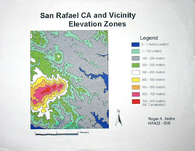
It's funny how things come full circle sometimes. When I graduated from college, my final GIS project was a map of elevation zones surrounding Mt. Tamalpaias in Marin, CA. The big deal about that project was the chance to use the Sun UNIX workstations that were ordinarily only accessible to graduate students and faculty. Those machines had the full version of ArcInfo needed to work with raster data sets, unlike the PC ArcInfo version which we had in the NR labs. As I recall, in order to complete the project, I had to download the correct USGS DEM, run a bunch of RECLASS commands to create elevation zones, convert the reclassified GRID into polygons, and finally bring it all into ArcView 3.x to make a map. I must have been pretty proud of the final result, because I saved the single printout I made of the map for almost 10 years. Recently, I've begun to work with elevation DEM's again, and among other things, have been using them to represent elevation and surface relief in maps. The ideas are similar to those used in that NR422 project, but the tools are completely different. So while I was happy to make something that looked like this in 1999:

It actually is a pretty lame map, so let's see if we can make something now that looks more like this beautiful map from Encyclopedia Brittanica

Friday, August 29, 2008
OGR wkb formats
types = { 'Point': ogr.wkbPoint,
'LineString': ogr.wkbLineString,
'Polygon': ogr.wkbPolygon,
'MultiPoint': ogr.wkbMultiPoint,
'MultiLineString': ogr.wkbMultiLineString,
'MultiPolygon': ogr.wkbMultiPolygon,
'GeometryCollection': ogr.wkbGeometryCollection
}
'LineString': ogr.wkbLineString,
'Polygon': ogr.wkbPolygon,
'MultiPoint': ogr.wkbMultiPoint,
'MultiLineString': ogr.wkbMultiLineString,
'MultiPolygon': ogr.wkbMultiPolygon,
'GeometryCollection': ogr.wkbGeometryCollection
}
Subscribe to:
Posts (Atom)